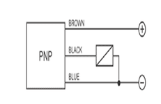
Sometimes we are facing problem with reading the diagram of sensors in industry. Below we try to explain different types of sensor diagram.
3-Wire PNP Sensor:
Here BROWN wire is +24V and BLUE wire is -24V which is supply voltage of sensor. BLACK wire is output. When object in-front of sensor then output voltage is +24V. Load is connect in output BLACK wire and another point of load is connected to -24V. Then load will be activated.

3-Wire NPN Sensor:
Here BROWN wire is +24V and BLUE wire is -24V which is supply voltage of sensor. BLACK wire is output. When object in-front of sensor then output voltage is -24V. Load is connect in output BLACK wire and another point of load is connected to +24V. Then load will be activated.

4-Wire Sensor:
Supply +24V in BN wire and -24V in BU wire. Here is two types of output; NO and NC. BK is NO output where as WH is NC output. If object is found in in-front of sensor then we will get -24V in BK wire. In normal condition, we will get -24V in WH wire. When object in-front of sensor then, output of WH is cut (No voltage).
